
The process of removing, replacing, and reinstalling the F1 tip ejector pusher upper and lower slide mechanisms require great care, a high attention to detail, patience, and steady hands. Please dedicate a good work area with good lighting and space where small parts can be located should they pop/fly out during disassembly. Pipette damage and lost parts may occur if attention to detail is not maintained. Please proceed at your own risk.
Finnpipette F1 and F2 Tip Ejector Mechanism Replacement – Pusher Upper Part and Lower Slide.
These instructions are applicable for both single channel and multichannel Finnpipette F1, F1 ClipTip, and F2 pipettes.
Disassembly Process:
Step 1:
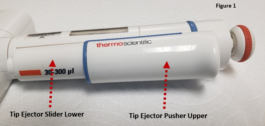
The ejector mechanism is made up of two components: the tip ejector pusher upper part and the tip ejector slider lower part. Check and become familiar with these parts.
Step 2:
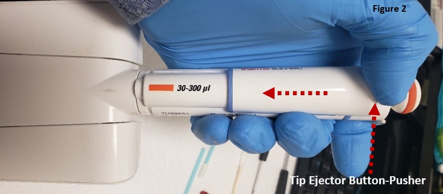
Press the ejector button down and hold.
Step 3:
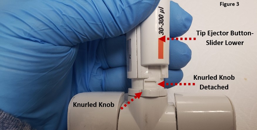
Gently rotate the white colored knurled knob clockwise to detach it from the tip ejector slider lower part.
Step 4:
With your thumb, gently push upward on the tip ejector pusher upper part to separate it from the tip ejector slider lower piece, per figure 4.
Note: You may need to use a small-bladed tool like a screwdriver to gently pry up one side of the tip ejector upper part if it does not come detached when pressing upward with your thumb. See figure 4.
Notice: The blue colored backside of the tip ejector pusher upper part contains:
- Left & Right-side rail tabs.
- Grooved cog wheel lines.
- Lower locking tab
Ensure none are broken off or missing. If so, replace.
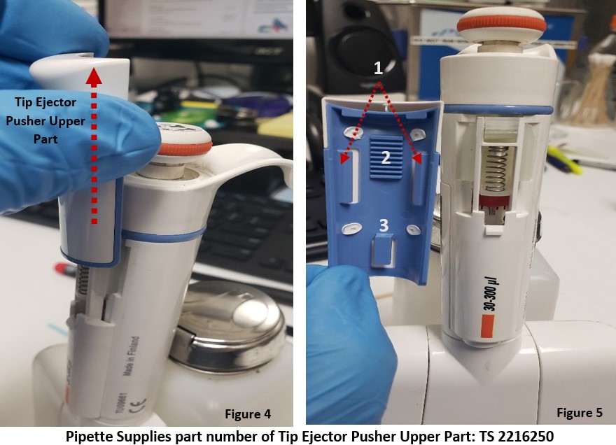
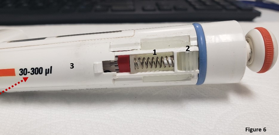
Observation: With the tip ejector pusher upper part removed, notice the components of the tip ejector slider lower part:
- Tip ejector spring: (TS 1132820)
- Cog wheel: (TS 1063370)
- Tip ejector slider lower part: (varies based on imprinted volume size [F1, F2])
These parts may pop off and get lost, be careful.
Step 5:
Gently lift outwards the cog wheel assembly, while pushing the entire tip ejector slider assembly lower part upward.
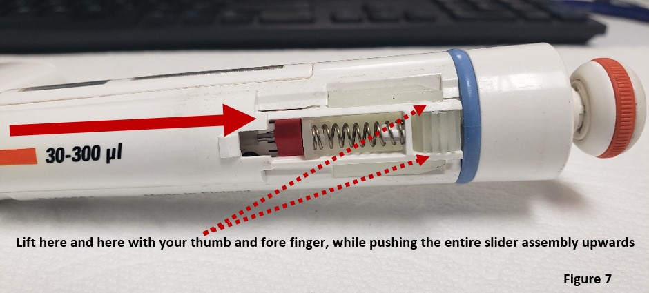
With the ejector slider lower part removed, the pipette will look as pictured in figure 8.

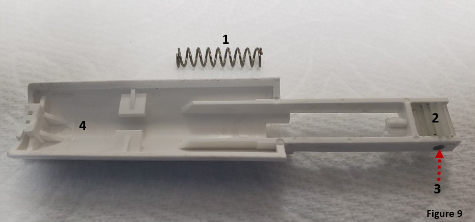
Step 6: Remove and replace parts (F1, F2) as needed:
- Tip ejector slider spring
- Cog Wheel
- Cog Wheel Pin
- Tip ejector slider lower assembly
Reassembly Process:
Step 7:
Insert new or existing spring back onto the upper (A) and lower (B) posts as shown in figure 10. Replace the pin in the cog wheel and then the cog wheel itself, as needed.
Notice: Support tabs C and D in figure 10 will be fitted into post E on the pipette body.
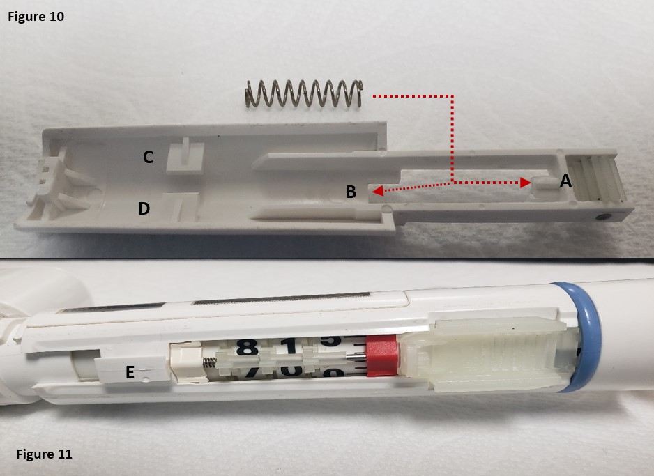
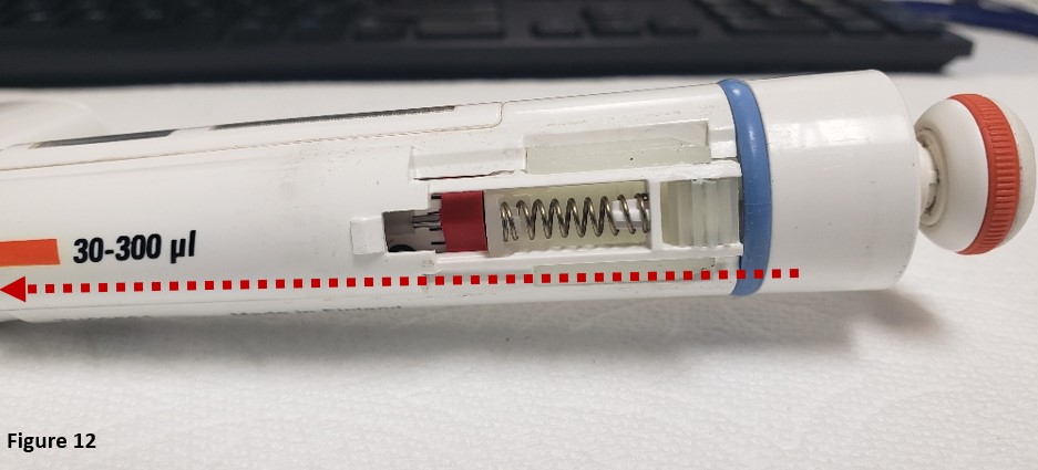
Step 8: Align tabs C & D into post E from figures 10 and 11. Fully slide the Finnpipette F1 / F2 tip ejector slider lower part back onto the pipette body as shown in figure 12.
Step 9:
As recommended by ThermoScientific Technical Support, place a “minute” amount of TS 3300200 1g grease onto a foam swab or lint-free towel. Very lightly grease the cog wheel with a very small of grease.

Step 10:
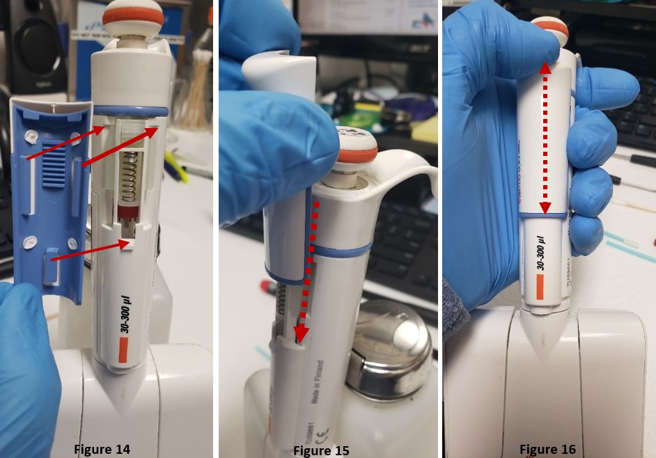
Refer to step 4, figure 5 by aligning the left and right-side tabs with the pipette ejector slider lower part, as in figure 14.
Step 11:
Slide the ejector pusher upper part back onto the pipette, as shown in figure 15. It should snap/click back into place once seated properly.
Step 12:
Lastly, press the tip ejector button a few times to ensure it is seated and working properly (Figure 16). Then test by loading and ejecting tips. Recheck your work, if needed.
Related Posts:
Finnpipette Digital (Model 4500) Single Channel: How to Service and Replace the Tip Ejector Assembly
Finnpipette Novus Error Codes
Types of Pipette Tips
Pipette Parts – Life Span, Life Cycle, and Performance
Disclaimer: Any action you take using the information on this website is strictly at your own risk. The information herein does not constitute professional advice and is general in nature. We make no warranty that this information will meet your requirements, be safe, accurate, or error-free. Pipette Supplies, Inc. is not responsible for any errors or omissions, any results obtained from the use of this information, or any loss or damage arising out of the use of this information. This site is for educational purposes only.
Fair Use: Copyright Disclaimer under section 107 of the Copyright Act of 1976, allows for “fair use” for purposes such as comments, criticism, teaching, scholarship, news reporting, and research.
Fair use is permitted by copyright statute that might otherwise be infringing.