
The process of removing, replacing, and reinstalling the Research Plus sealing ring requires great care, a high attention to detail, patience, and steady hands. Please dedicate a good work area with good lighting and space where small parts can be located should they fly out during disassembly. Pipette damage and lost parts may occur if attention to detail is not maintained. Please proceed at your own risk.
Recommended Parts and Items
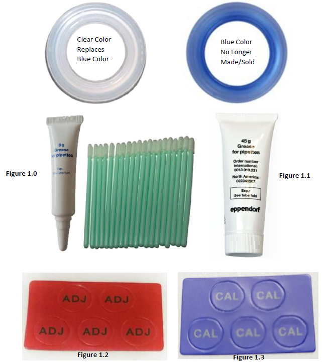
- 100uL-1000uL Research Plus Sealing Ring: EP 3120066047
- Grease Options
- 8 Grams of Eppendorf Silicone Grease w/ Swabs: EP 0013022153 (Figure 1.0) or,
- 45 Grams Eppendorf Silicone Grease: EP 022348507 (Figure 1.1)
- If adjustment is needed:
- Sticker Options
- Red colored adjustment sticker: EP 3120636005 (Figure 1.2) or,
- Blue colored calibration sticker: EP 0012521848 (Figure 1.3)
- Adjustment Tool: EP 3120633006
- Research Plus Safety Plug: EP 3120639004/1
- Sticker Options
Disassembly Process for Sealing Ring Replacement:
Step 1:
Identify and make yourself familiar with the main components that will need to be used to gain access to the internal sealing ring.
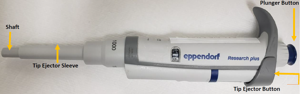
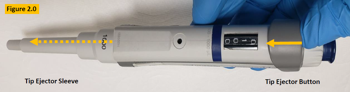
Step 2:
Press down and hold the tip ejector button to lower the tip ejector sleeve. Figure 2.0.
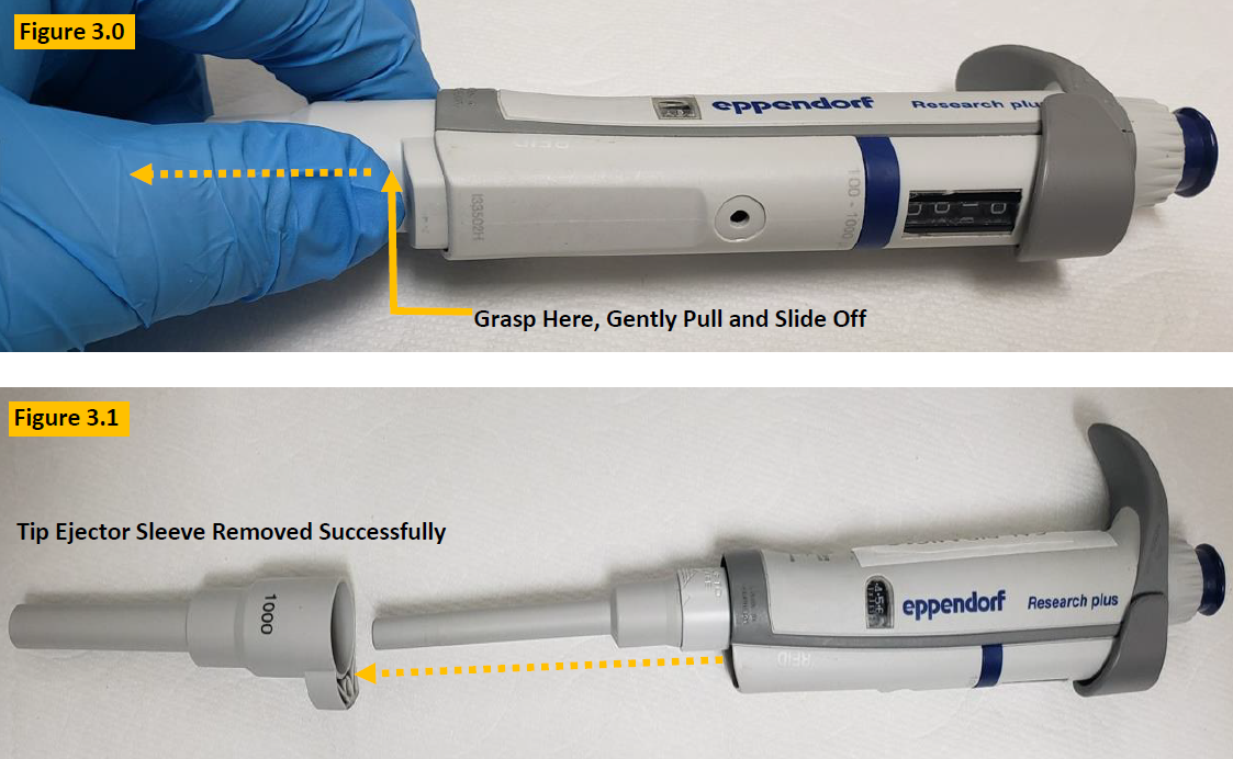
Step 3:
With the tip ejector button pressed, gently grasp the tip ejector sleeve, and gently slide and pull it off from the
pipette body. Lay aside for reassembly. Figure 3.0.
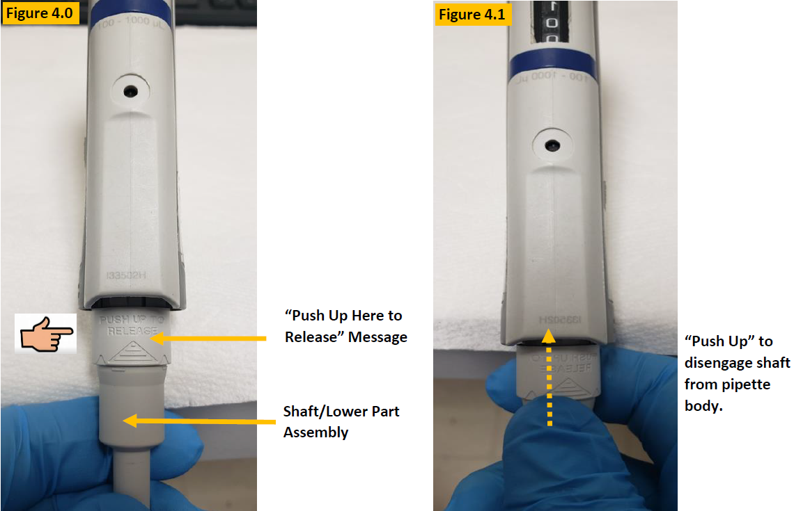
LOOK: Notice the engraved words on the shaft (lower part) “Push Up Here to Release” as shown in Figures 4.0 and 4. 1.
Step 4:
Push up gently but firmly to disengage the lower part assembly (shaft) from the pipette body. See Figure 4.1.
COMMENT: Figure 4.3 is an up close picture of the lower part assembly (Shaft). Familiarize yourself with the component names:
- Piston Cap
- Shaft
- Push up/release.
- Locking tabs/rings

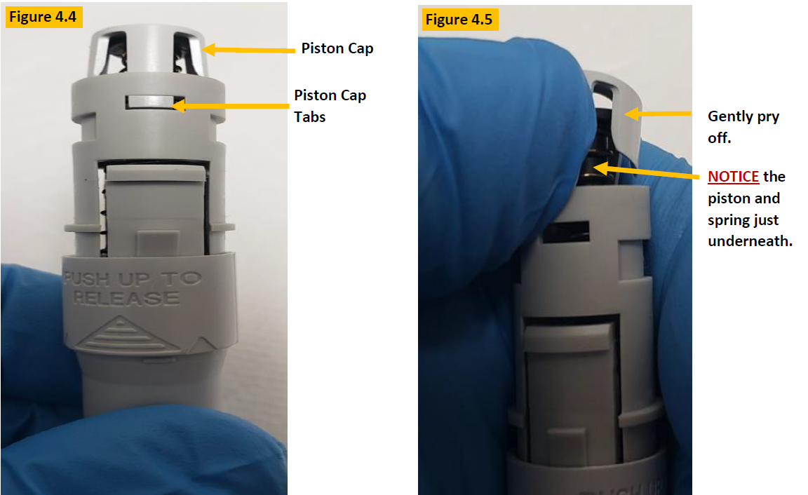
CAUTION: The piston cap holds the piston and piston spring in place, under tension. Use caution when removing the piston cap to prevent the spring and piston from flying out. Notice the piston cap tabs that hold it in place as shown in Figure 4.4.
Step 5:
Gently pry off the piston cap, as shown in Figure 4.5. Use your thumb to keep tension on the cap until you can grasp the piston and spring that are just below the piston cap. Remove the piston assembly from the shaft.
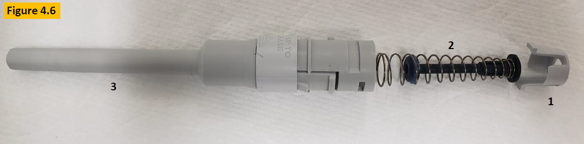
COMMENT: Observe the contents of the lower part after disassembly:
- Piston Cap
- Piston Assembly with spring & sealing ring
- Shaft/Lower Part
Step 6:
Inspect the piston, spring, sealing ring, and lubricant for damage, chemical splash, etc. as in Figure 4.7. Clean any component with a lint-free cloth (i.e. kim wipe) and 70% IPA as needed, and or replace if necessary.

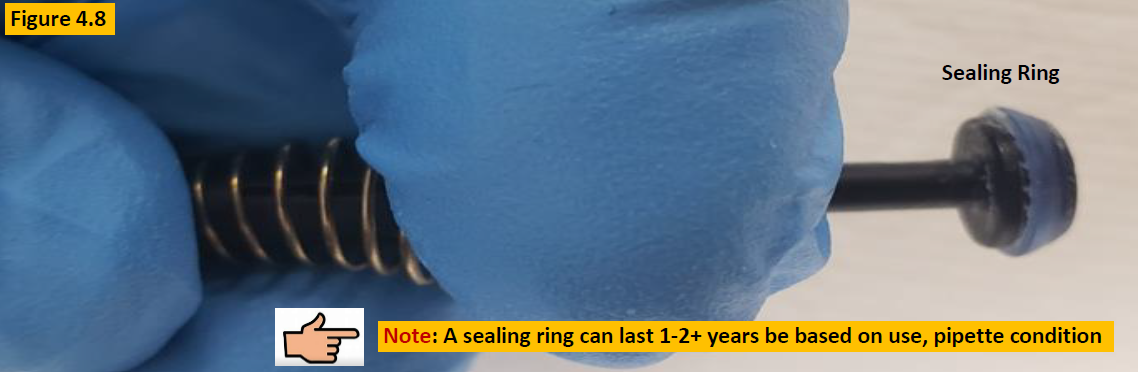
Step 7:
To clean the sealing ring and remove old lubricant, collapse the piston spring (Figure 4.8) so the sealing ring is unobstructed. Clean the sealing ring with 70% IPA and lint-free cloth. Inspect the sealing ring for cracks, splits, or wear. Replace as needed.
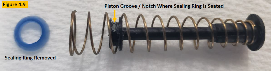
Step 8:
To replace the sealing ring, follow step 7 above, including cleaning removing the sealing ring from the piston with a
small-bladed tool. See Figure 4.9.
Step 9:
Ensure the piston, piston spring, and piston groove are clean and free of lubricant.
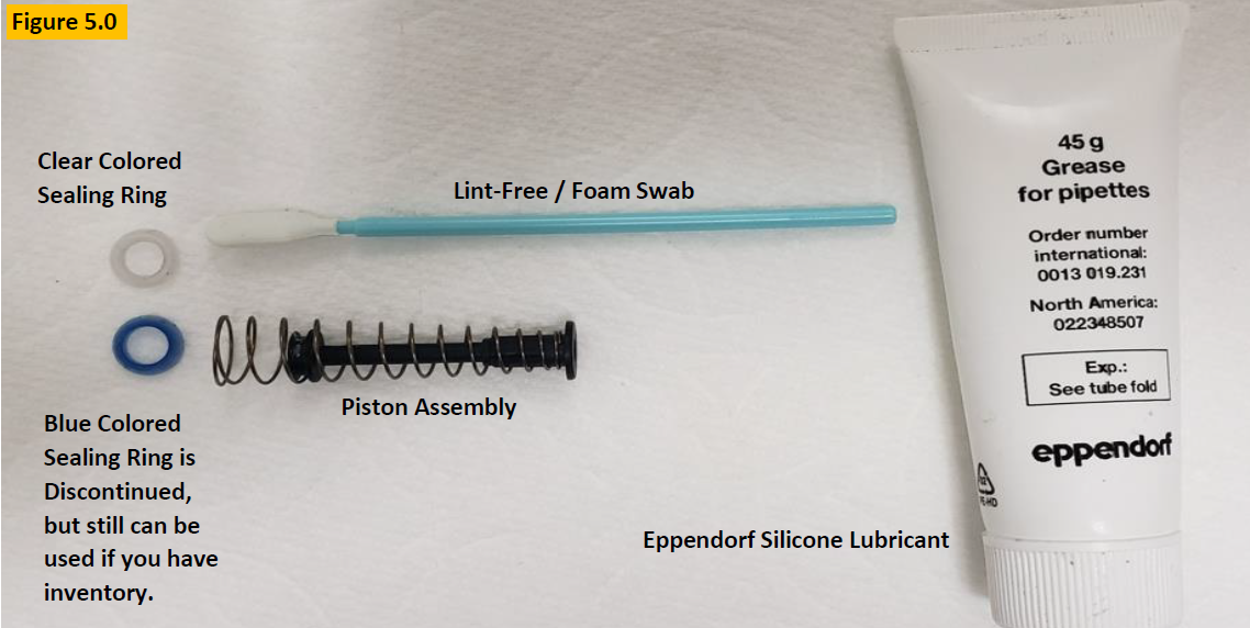
COMMENT: Per Figure 5.0, prepare your Eppendorf silicone grease, lint-free / foam swab, and Research Plus sealing ring for lubrication and installation.
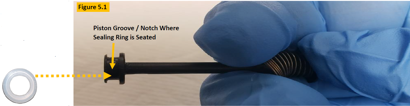
Step 10:
Collapse the piston spring as shown in Figure 5.1, to install the new sealing ring into the piston grooved / notched
position until seated fully.
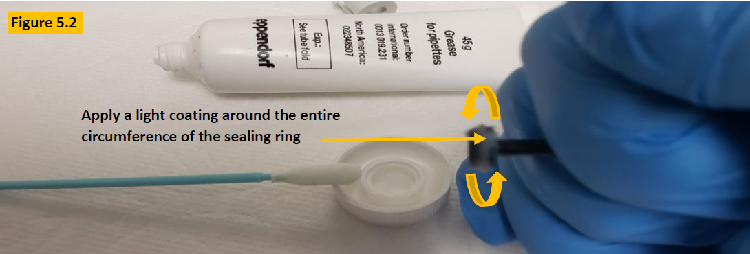
Step 11:
With the new sealing ring installed, apply a light coating (slightly visible to the eye) of Eppendorf silicone lubricant around the entire circumference of the sealing ring as shown in figure 5.2.
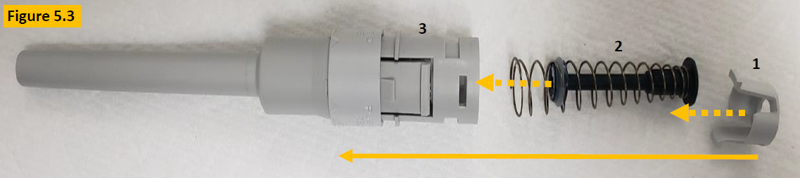
Step 12:
After installation and lubrication of the sealing ring, prep the lower part for reassembly as shown in Figure 5.3.
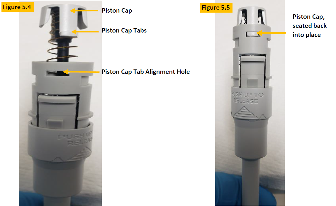
Step 13:
After placing the piston assembly back inside the shaft/lower part, place the piston cap over the end of the piston and
press down until the tabs align and click in place (Figure 5.5).
Step 14:
Insert the lower part assembly / shaft back into the pipette body opening and is fully attached. Figure 5.6.

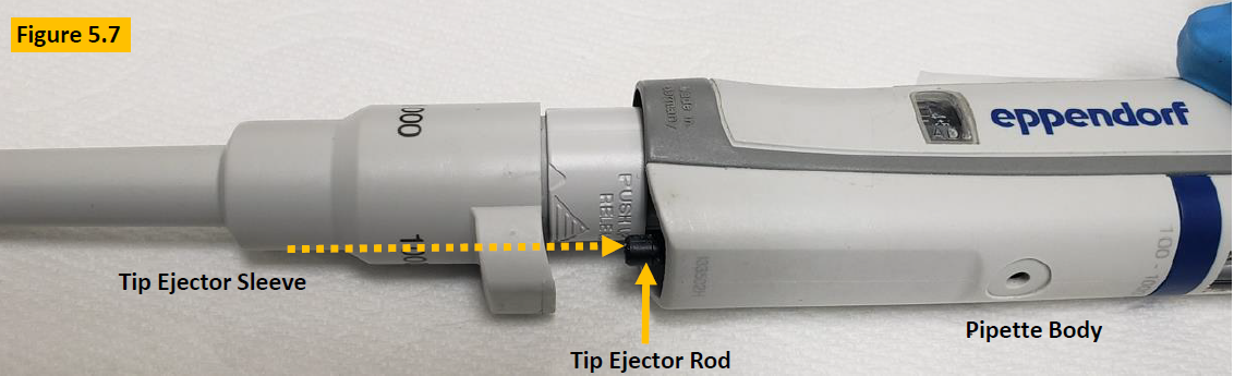
Step 15:
Press and hold the tip ejector button down. The black colored ejector rod will protrude from the body. Align the ejector sleeve with the ejector rod and click the tip ejector sleeve back onto the pipette. Figure 5.7.
Step 16:
Once the pipette is reassembled, allow it to equilibrate to ambient conditions for at least 60 minutes.
Step 17:
Perform a liquid leak test at nominal volume and then confirm pipette accuracy and precision, and desired results are obtained.
Adjustment Process – Only If Needed
COMMENT: Figure 5.8, If the volume that is aspirated and dispensed is not desirable, then recheck your work as well
as consider…
- Is the ADJ window digits at “0”?
- A possible calibration adjustment

Step 18:
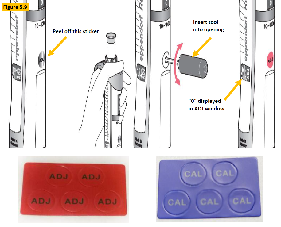
Figure 5.9. Peel off the red, blue, or gray colored ADJ or CAL sticker that covers the adjustment hole.
Step 19:
Press down and hold the tip ejector button, then insert the adjustment tool (EP 3120633006) into the opening and rotate until ADJ window aligns the “0” with the carat symbol.
Step 20:
With ADJ window set to “0”, recheck to see if desired volume is now achieved.
Step 21:
Affix replacement CAL or ADJ sticker over opening after tool is removed.
NOTE: If desired volume is not achieved, proceed to step 22.
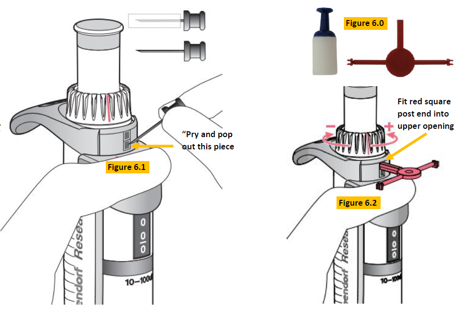
Locate: Part number EP 3120639004/1, calibration adjustment tool as shown in Figure 6.0.
Step 22:
Press down and hold the tip ejector button. Insert the safety pin into the bottom square and pry/pop it out (Figure 6.1).
Step 23:
Insert the square post end of the red colored tool into the top gray square and push it downward so the red colored square post fits into the open slot (Figure 6.2). Adjust counter-clockwise to increase volume. Adjust clockwise to decrease volume.
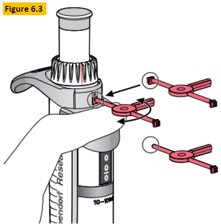
Step 24:
Once adjustment is completed, insert the replacement tab portion into the bottom opening and twist off until the tab
is locked into position (Figure 6.3).
Step 25:
Check the pipette performance on a gravimetric balance to confirm desired results are obtained.
Related Posts:
How to Calibrate an Eppendorf Research Plus Fixed Pipette
Eppendorf Reference 2: How to Replace the Volume Catch (and Access the Counter Assembly)
Eppendorf Xplorer Battery Replacement Instructions
Top 10 Crimes Committed Against Pipettes
Disclaimer: Any action you take using the information on this website is strictly at your own risk. The information herein does not constitute professional advice and is general in nature. We make no warranty that this information will meet your requirements, be safe, accurate, or error-free. Pipette Supplies, Inc. is not responsible for any errors or omissions, any results obtained from the use of this information, or any loss or damage arising out of the use of this information. This site is for educational purposes only.
Fair Use: Copyright Disclaimer under section 107 of the Copyright Act of 1976, allows for “fair use” for purposes such as comments, criticism, teaching, scholarship, news reporting, and research.
Fair use is permitted by copyright statute that might otherwise be infringing.